

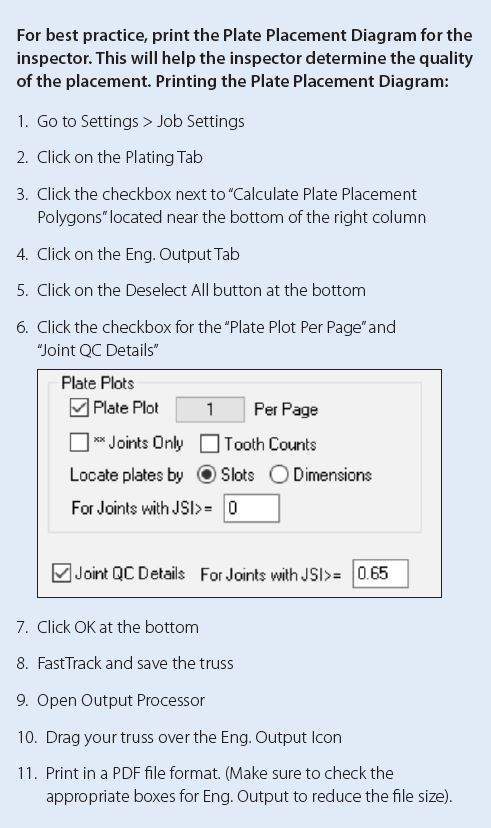
Imagine a third-party truss inspector is in the yard checking truss plates as part of quality control. The plate placement diagram indicates the web needs twenty-five teeth; however, the inspector counts twenty. Even though the shop positioned the plates as designed, is the plate placement correct?
In short, yes. The size and placement are acceptable. The inspector is seeing the rounding done by the software. Alpine software will engineer plates by the coverage of the plate on each wood member as well as the plate’s angle. The Plate Placement Diagram is produced by the software and will highlight the expected number of teeth for each member covered, as required by TPI. Note that this number is rounded to the lowest whole tooth. The diagram will also include additional placement considerations for quality control.
Plate Placement & Teeth – The Technical Answer
Counting teeth on the end or edge of members
The teeth on the end and edges of the connected members should be included. The Alpine Software adjusts for some “dead zones” at the ends and edges of the members, these dead areas are accounted for in the plate size. Understanding the end and edge distances, the ES Report (ESR1118) has two values for plates, “net” and “gross”. On the next page, Table 1 illustrates how the net capacity per square inch of plate is larger than the gross capacity. It is important to remember the capacities given in this table are on a per square inch of covered wood. The gross area omits the end and edge distances. This reduces the capacity of the entire plate to account for losses in the dead zone.
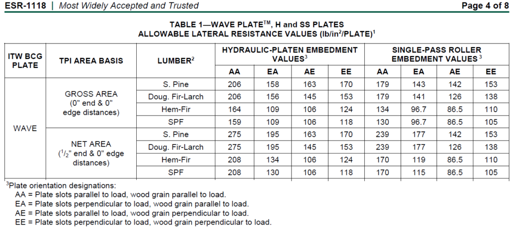
To illustrate, a 1.5×3 plate holding a compression web to a chord. The web is DF-L. The plate is in the AA orientation on the web. The plate is entered on the web/chord joint. Per Table 1, the gross capacity is 206Psi/plate. The available area for the gross capacity is 1.5”x1.5” or 2.25 in2. To calculate the plate’s tooth holding capacity, the equation is 2.25 in2 x 206Psi = 463.5 lbs.
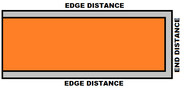
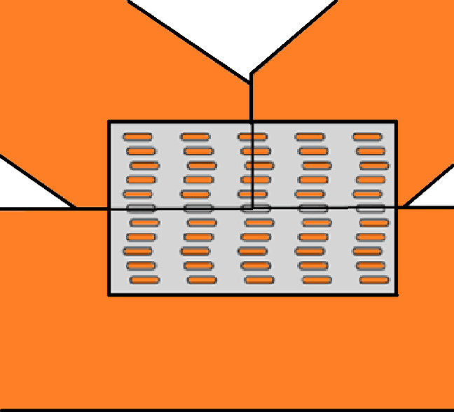
When using the Net Area Method, the tooth holding capacity is not reduced, and the end distances are removed from the available plate area (see orange areas in Figure 1). For example, 6×6 Plate on a 2×4 the covered area would be 3.5” wide by 2.5” long. The table shows the end distance for wave plates is ½”. The National Design Standard (NDS) addresses this information as well as specify the fastener (plate teeth) capacity reduction due to distance from the ends of members. Whereas the gross area uses a reduced per-tooth capacity over the entire covered area.
How the software accounts for the end and edge distances of the connected members
Founded on extensive research, the IntelliVIEW Software calculates the capacity of plates based on the area of the member covered and angle of the plate. This produces a capacity per square inch of coverage area. The software then uses this capacity per square inch to calculate the minimum plate area. Understanding how many teeth per square inch there are in the plates and using the covered area, the software calculates the number of teeth in the member.
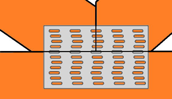
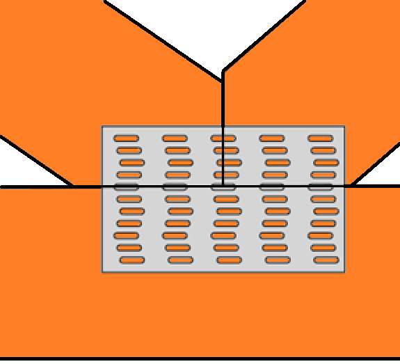
For example, two webs and a bottom chord being joined by a 3×5 plate, the IntelliVIEW Software calculates that each web needs 2.80 in2 of plate coverage to be able to transfer the loads, and 6 in2 in the chord. The CQ factor would allow the shop to have a placement tolerance of ¼”. The plate is centered where all three members touch. In this location the chord will have a Gross Plate Area of 7.5 in2 . With the ¼” placement tolerance, the Gross Area in the bottom chord becomes 1.25”x5”, 6.25in2. Alpine’s wave plate has 8 teeth per square inch. The number of teeth in the chord is calculated: 1.5 x 5 x 8 = 60 nominal teeth, Figure 2. If the shop shifted the plate down, the Gross Area = 70 teeth (Figure 3). If the plate were shifted up, the Gross Area = 50 teeth.
Alpine engineers thoroughly tested the design of each connector plate type. The results are expressed as capacity per square inch of plate into the wood member. The IntelliVIEW Software calculates the smallest feasible plate for each joint. After many checks are performed and the smallest plate is determined, the software analyzes the area of coverage (in square inches) and multiplies that area by eight to report the number of whole teeth required. This calculation sometimes will result in a perfectly acceptable plate location, but the number of teeth may not match the reported number due to rounding. If the plate is located as noted on the Plate Placement Diagram, the joint will be sufficient to transfer the expected loads regardless of the number of teeth present.
For more information or questions, please contact your Alpine Structural Engineer.
Reference(s):
- Truss Plate Institute (TPI) = ANSI/TPI 1 – 2014
- National Design Standard (NDS) 2015 edition, National Design Specification for Wood Construction ANSI/AWC. Approval date September 30, 2014
- ESR1118 = ICC-ES Evaluation Report ESR-1118 https://icc-es.org/report-listing/esr-1118/