
Designing long-span trusses starts with a clear definition. Establishing what constitutes a long-span truss sets expectations early, helping to drive smarter design, manufacturing, and logistics decisions from the outset.
Defining Long-Span Trusses
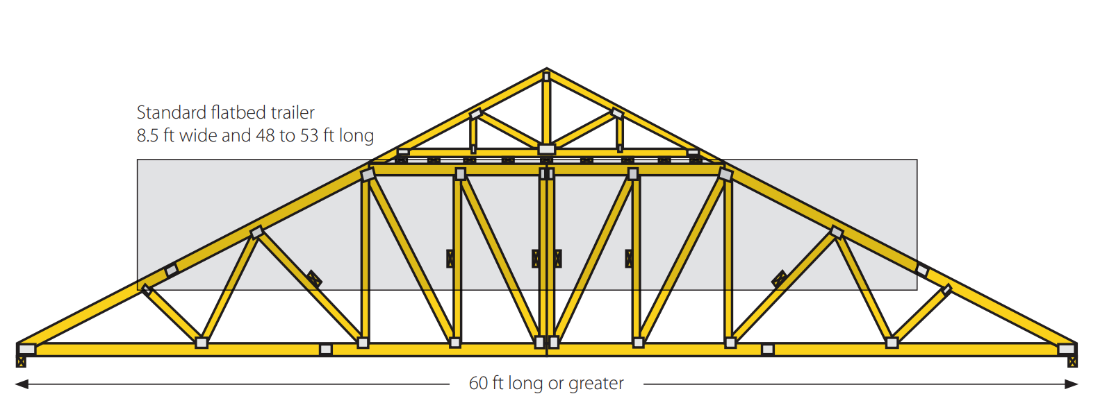
According to the Building Component Safety Information (BCSI), long-span trusses are defined as trusses with a clear span of 60 feet (ft) or greater. In practice, however, a good working definition is any truss that cannot be transported as a single unit. In other words, does it fit on a typical flatbed trailer? If not, it is a long-span truss.
A standard flatbed trailer is typically 8.5 ft wide and 48 to 53 ft long (see Figure 1). When trusses exceed these transport limitations, they present unique challenges for the truss manufacturer, contractor, and erection contractor (or framing contractor).
This article focuses on the challenges faced by truss manufacturers and highlights how Alpine® Engineers help support navigating these complexities.
Reviewing Construction Documents
Before starting the design process, confirm that the following questions can be clearly answered based on the project’s construction documents. If information is missing or unclear, contact the building designer to obtain the necessary details. The checklist below serves as a practical reference to support a thorough and efficient design review.
Building & Site Parameters
❑ Construction Type: Identify the primary building construction method.
❑ Wall Specifications: Confirm the type of wall construction and wall heights.
❑ Occupancy & Use: Verify the occupancy and intended use of the building.
❑ Exposure: Note the presence of open sides.
Structural & Load Requirements
❑ Bearing Points: Locate all interior bearings.
❑ Mechanical & Special Loading: Identify requirements for HVAC equipment, movable partitions, or material handling systems.
❑ Drainage: Confirm any special drainage provisions that will be required for flat or sloping-flat trusses.
Logistics & Assembly
❑ Field Splices: Determine if the framing contractor requires trusses to be field spliced.
Framing Contractor Assessment
The next step, and equally important, is to assess the capabilities of the team on-site. An understanding of available experience, equipment, and installation expertise helps identify potential constraints early while reducing potential installation problems. Consider the following:
❑ Experience: Is the framing contractor experienced in handling long-span trusses?
❑ Equipment: Does the framing contractor have proper lift equipment, such as an adequate crane and a spreader bar of the correct length?
❑ Support: Will the framing contractor be willing to install temporary scaffolding down the center of the building until the roof deck is secured, and all bracing is installed?
❑ Knowledge: Does the architect, engineer, and framing contractor have—and understand—BCSI truss handling and bracing requirements?
❑ Supervision: What is the contact information for the architect or engineer responsible for design and field supervision?
Special Considerations
To ensure structural integrity and ease of handling for long-span trusses, the following recommendations help reduce risk, enhance efficiency, and promote consistent structural performance:
❑ Lumber: Dense or MSR lumber is recommended for the top and bottom chord. For improved handling, 2×8 members are recommended for both top and bottom chord sizes.
❑ Configuration: For better handling and stability, long-span trusses should be two-ply. These may be spaced greater than 24” O.C. (on center).
❑ Field Splices: For field splices, a jack-scab is required on both faces. Please contact your Alpine Engineer for guidance.
❑ Installation: It is recommended the framing contractor review the video “Proper Erection and Bracing Procedures” and that the engineer be present at the jobsite while trusses are being installed.
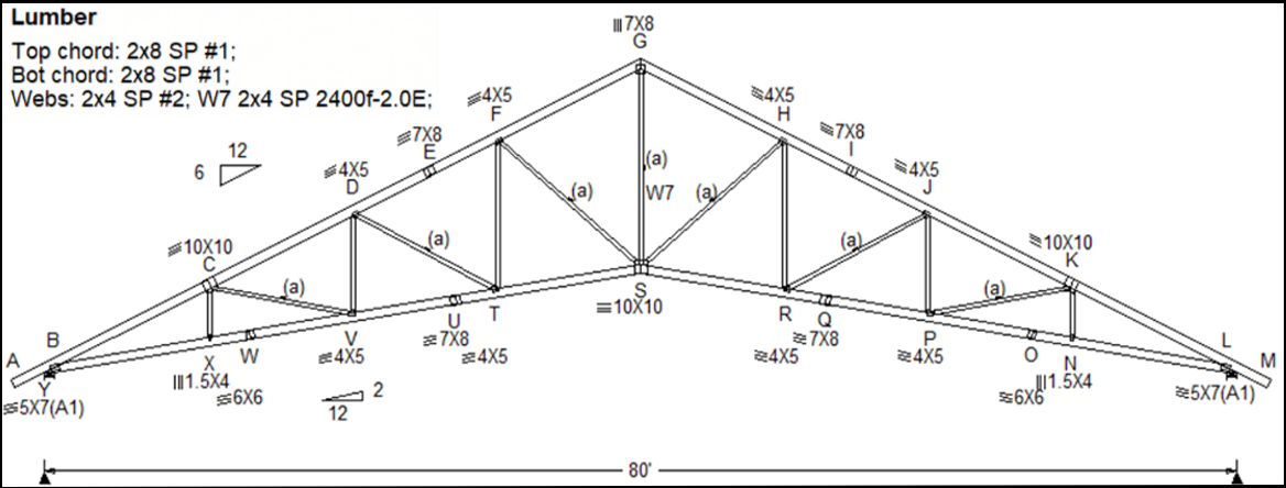
Design Example With an 80-FT Scissor Truss
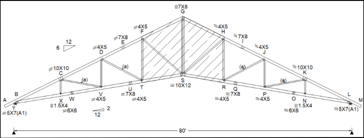
With the above checklists addressed and a clear path forward, this section provides an example to help illustrate key design concepts in application. The following explores an 80-ft scissor truss with a 6/12 top[1]chord pitch and 2/12 bottom-chord pitch.
Step 1: The Baseline Design
The first step is to revisit the checklist outlined earlier to ensure all project requirements are understood. Once verified, design an 80-ft truss using all design criteria provided in the construction documents. This full-span design serves as the baseline for developing the two splice segments (see Figure 2).
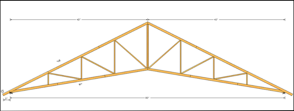
Step 2: Field Splicing and Segmentation
In this example, the project requires a field-spliced truss. The most straightforward approach is to design two 40-ft trusses that can be connected in the field. However, a critical requirement is to use the same lumber grades, plate sizes, and web-bracing requirements specified in the original 80-ft truss design. Using materials or plate sizes appropriate for a standard 40-ft truss will result in inadequate capacity. Once assembled, the system functions as an 80-ft long-span truss, not two independent 40-ft trusses.
Additionally, because the full truss will be divided into two halves, two vertical webs must be incorporated at the peak of each 40-ft truss, as illustrated below (see Figure 3).
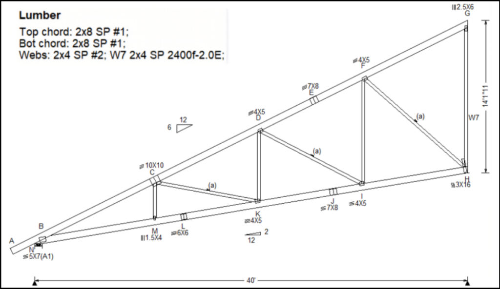
Step 3: Creating the Segment Designs
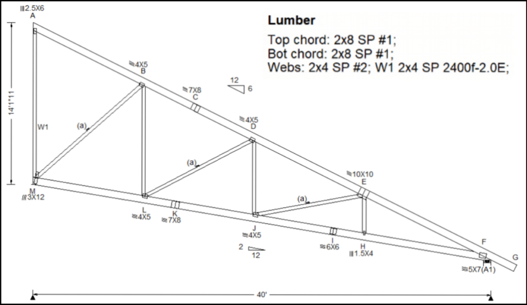
The design for the left 40-ft segment of the overall 80-ft long-span truss is shown in Figure 4. The same design process is then applied to develop the corresponding 40-ft right-side of the truss, shown in Figure 5.
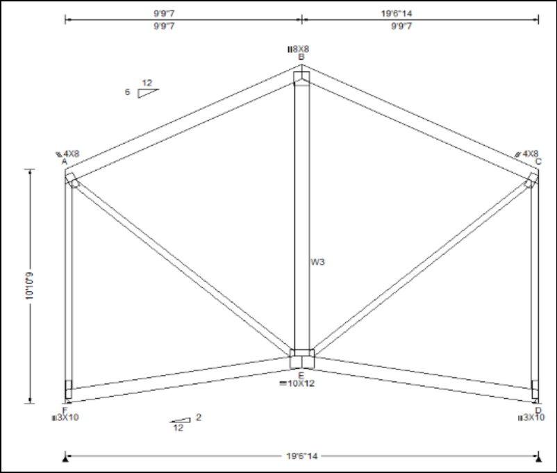
Step 4: The Jack-Scab Truss
The next step is to design the two-ply jack-scab truss. This component must include the full top-chord section on both sides up to the peak, along with the full bottom-chord section. Matching webs are required to ensure proper transfer of forces through each chord and web member (Figure 6).
Note: The connection details between the jack-scab truss and two 40-ft truss halves must be provided by an Alpine Engineer or another Registered Design Professional (Figure 7).
Jobsite Installation Guidelines
Once all truss sections have been designed, fabricated, and delivered to the jobsite, BCSI provides several key guidelines to ensure proper and safe installation:
❑ Professional Oversight: Engage a Registered Design Professional to prepare a temporary restraint and bracing plan and to oversee the process. This is required by the International Building Code.
❑ BCSI Standards: Review and understand the latest BCSI documents before installation begins.
❑ Safety Planning: Develop a safe and effective truss installation plan and ensure all crew members understand their responsibilities.
❑ Experienced Personnel: Use personnel experienced in installing long-span trusses, particularly those spanning 60 ft or more.
❑ Pre-Installation Inspection: Inspect all trusses prior to installation to verify they are in suitable condition.
❑ Damage Documentation: Document any truss damage before installation and ensure all repairs are completed in accordance with repair details prepared by the Truss Designer or a Registered Design Professional.
❑ Support Stability: Confirm that all walls and supporting structures are stable, properly restrained, and adequately braced prior to setting trusses.
❑ Equipment Readiness: Verify that all necessary lifting equipment and materials are on site and ensure the crane operator understands the unique hoisting requirements associated with long-span trusses.
Requirements for Spans Exceeding 80–90 FT
Long-span trusses exceeding 80 ft require additional coordination and design consideration. For projects over the 80-90 ft range, the following information and requirements should be reviewed in collaboration with an Alpine Engineer to ensure structural performance.
Checklist:
❑ Contact Information: Provide the name and phone number of the architect or engineer responsible for the design and field supervision.
❑ Double Trusses: Alpine normally requires double trusses on spans above 90 ft. These trusses may be spaced out at intervals greater than 2 ft O.C. and fastened together either at the truss plant or on the ground at the jobsite. All double trusses must be lifted as pairs. Acceptance of double trusses should be confirmed early in the design process.
❑ Lumber Grade: Truss chord members shall be MSR lumber or visual grade of Select Structural or Dense Select Structural to meet the strength and consistency requirements.
❑ Analysis: For spans greater than 90 ft, Alpine’s standard analysis is required. Empirical analysis methods will not be permitted for these applications.
❑ Compression Limits: Maximum permitted axial compression force in chord members is 25,000 pounds (lbs.) per ply.
❑ Materials: Roofing and ceiling materials must be clearly identified.
❑ Dead Loads: Design dead loads must be verified to account for the weight of all specified materials, including the weight of the trusses.
❑ Bracing: All continuous lateral web bracing must be eliminated by means of increasing web grade and/or web size, or by use of Alpine Web Block, T-bracing, L-bracing, or scab reinforcement.
❑ Environmental Loads: Trusses must be designed for all code-required environmental loads, including unbalanced snow and wind loads, in accordance with the ASCE-7.
❑ Piggyback Bracing: Flat top chord of all piggybacked trusses must be laterally braced with structural sheathing decking.
Addressing these considerations early in the design process helps reduce risk and improves jobsite
Addressing these considerations early in the design process helps reduce risk and improves jobsite coordination, while supporting an overall execution of long-span trusses. For further guidance or project-specific support, contact your Alpine® Engineer.
Reference(s):
- Building Component Safety Information (BCSI)
- International Building Code 2024 (IBC)