
A Truss Design Drawing (TDD) includes specific information1 for structural engineers and building designers: truss profile, plates, loadings, wind speed, codes, enclosure, exposure, reactions, deflections, materials, bracing, bearings, etc. The maximum reactions are the most important values in a truss design. These reactions are used for designing structural components (e.g., column, lintel, connector, dowel, and foundation).
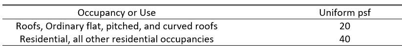
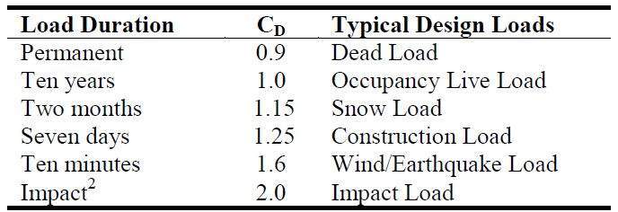
Figure 1 is a typical roof TDD. Sections A, B, and D are important in determining the correct maximum reactions in C. A shows gravity loading and the load duration factor used to design a truss. The proper loadings indicate the least value per code(s). For example, the minimum uniform live loads are 20psf for roof and 40psf for floor trusses per ASCE7-162, Table 4.1. Also, the load duration factor should be 1.25 for roof, 1.15 for snow, and 1.00 for floor trusses per NDS 20183, Table 2.3.2.
B details the wind, snow, and building code information. In one job, the wind/building code, wind speed, risk category, and exposure must be the same (Wind enclosure can be mixed within a job). If there is a truss which has different wind information, the truss will show wrong reactions in C. Also, dead loads in wind load case, shown as TCDL/BCDL in the Figure 1, cannot be larger than 60% of the dead loads in A. This came from the allowable stress design (ASD) loading combination, , to obtain the highest uplift per ASCE7-162, 2.4.1. The code and TPI standard should be the right version per county, city, or local regulation.
Truss deflection, connector plate types and sizes, Combined Stress Index for member (CSI) and bearings all need to be checked to ensure the stability of the truss. When any of these factors are inadequate for the truss, Alpine IntelliVIEW4 software displays a note in section D. This is especially important for a girder truss because these types of trusses are designed to support other trusses. For a girder truss, IntelliVIEW4 software highlights special loads including supporting loads on the truss. These special loads directly affect the maximum reactions in section C. Therefore, to obtain the correct values in section C, it is crucial to check the special loads carefully.
Once the loading criteria is correct the drawing can then be reviewed and signed by an Alpine Professional Engineer, typically within one business day. Always remember in the TDD, section C is the most important check point as sections A, B, and D will supply the information to obtain the correct values in C.
Reference:
- How to Read a Typical Alpine Component Drawing. HowToReadComponentDrawing-Rev7.pdf (alpineitw.com)
- ASCE7-16 Minimum Design Loads and Associated Criteria for Buildings and other Structures
- NDS 2018 edition for Wood Construction
- IntelliVIEW Suite: The software solution for Component Manufacturers (alpineitw.com)