Every truss design is evaluated for numerous criteria to determine if it is structurally sound. One of those checks is the capacity of the truss to resist buckling at a bearing location. This article focuses on checking out-of-plane buckling when a truss member is loaded in compression perpendicular to grain and Alpine’s solutions for trusses that fail the check.
What Changed & What Factors Impact the New Check
The reference standard for the wood truss industry, ANSI/ TPI 1-2014, introduced a check for truss members at reaction points for compression perpendicular to grain that may cause cross-grain buckling. These checks are typically applied at heel joints and interior bearing locations. The check addresses the potential for out-of-plane buckling at the bearing location when the heel joint or chord member is not restrained from buckling sideways. Without appropriate lateral restraint, the heel or chord member could buckle under load.
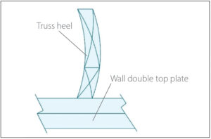
The main variables involved in the check are the width, depth, and stiffness of the members at the bearing location. When checking a heel joint, the depth is the deepest point measured from the bearing to the center line of the top chord. At an interior bearing location, the depth of the chord is used in the check. The stiffness is measured by modulus of elasticity (E value). A heel joint having a top chord member, bottom chord member, and slider, will use the lowest E value of all the truss members at the heel. Increasing the width or number of truss plies, reducing the depth as measured for this check, or using lumber with an increased E value will increase the compression perpendicular to grain capacity.
Options for Meeting the Buckling Check
When a multi-ply truss is being analyzed, additional ply-to-ply nailing of the truss members at the bearing location will give the truss an increased width for the purposes of the TPI check. This enhanced nailing will increase the compression perpendicular to grain capacity and may eliminate the need for restraint blocking. Single-ply and multi-ply trusses that are supported by hangers at the bearing location are not checked for the TPI buckling requirement. The hanger pocket flanges will provide the necessary out-of-plane restraint.
Alpine’s Solutions for Failed Truss Checks
For trusses that fail the TPI cross-grain buckling check, there are three solutions Alpine engineered. Each of these three options are available on the Alpine Blocking Reinforcement Detail.
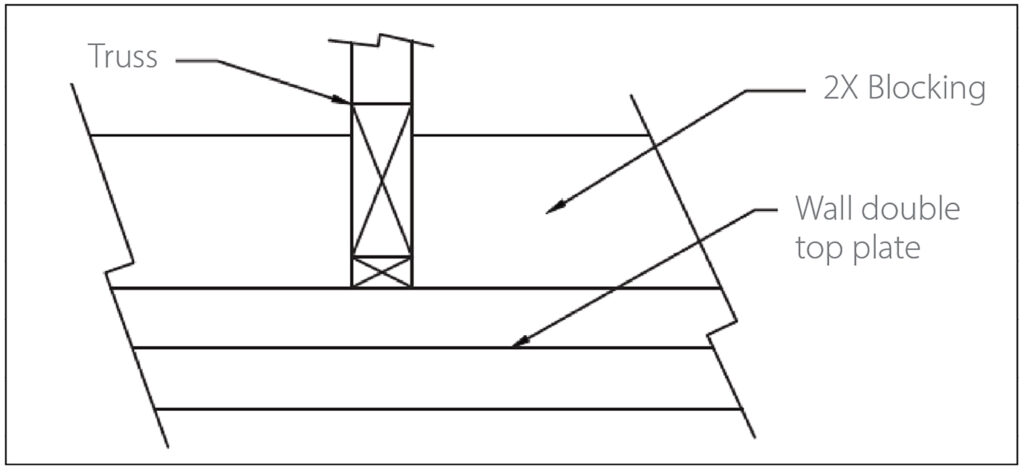
Option 1 – Blocking Between Trusses
Step 1: Apply blocking by using 2x stress-graded lumber attached perpendicular to and between trusses at the heel or interior bearing. Blocking is to be sized based on the blocking note which is located on the Alpine Truss Design Drawing. Blocking shall be placed on both sides of truss requiring reinforcement and sized to fit tight between trusses. See Figure 1.
Step 2: Attach blocking at each end to trusses with three equally spaced 0.131”x3” nails driven through truss members into end of block, or two equally spaced 0.131”x3” nails toe-nailed through block into truss members.
Option 2 – Scab Reinforcement
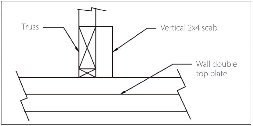
Step 1: Attach a vertical scab using 2×4 stress-graded lumber to one side of the truss at the bearing. The scab shall be the full truss depth at the heel. See Figure 2.
Step 2: Attach with two equally spaced staggered rows of 0.131”x3” nails at 4” on center. A vertical scab is not a replacement or substitution for bearing block requirements that are specified on the Alpine Truss Design Drawing.
Option 3 – Truss Attachment to Wall Sheathing
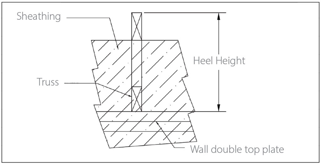
For truss heel heights between 9.25” and 15.25” and where the outside edge of truss heel aligns with the outside face of the wall studs below, wood structural panel sheathing extending above the top plate shall be fastened to truss with five 0.131”x2.5” nails into each end of truss members. The nail quantities are divided proportionately between the contacted truss members. The sheathing depth above the wall plate must meet or exceed the blocking reinforcement depth as specified on the Alpine Truss Design Drawing. Sheathing shall be attached to the wall in accordance with IRC2018 R602.3 and IBC2018 2403.6. See Figure 3.
Contact your Alpine Structural Engineer for additional information about out-of-plane buckling.
Reference(s):
- ANSI/TPI 1 2014 Section 7.3.8
- International Building Code (IBC) Section 2403.6
- International Residential Code (IRC) Section R602.3
- All images are created internally by the author

